Originally published on fcp.co
Peter Wiggins wrote:
We are very pleased to bring you one of the best Final Cut Pro X plugin construction tutorials you will find online. We are yet to see the building of FCPX On Screen Controls documented in such a detailed manner. Fox Mahoney puts a lot of knowledge and experience into this article that needs to be bookmarked by all plugin builders, developers and advanced users. Plus he’s very kindly uploaded the free HUD demo template!
If you haven’t been following Fox’s great OSC tutorials, the first two parts are listed below.
If you are a beginner, it would help to read these first.
Part Three
Most of the OSCs available in all the various filters (and generators) are exactly like the OSC used by the Poke filter. There are, however, several notable mostly unique OSCs available that will allow you to apply their properties in inventive ways. Let’s take a look:
(Click to make images bigger)
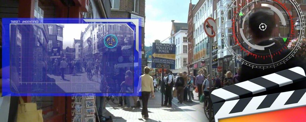
Blur Filters OSCs:
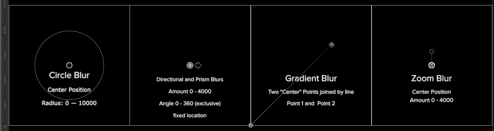
Distortion Filters OSCs
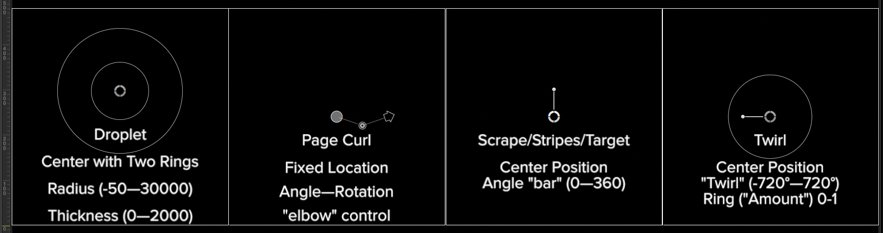
Stylize Filters OSCs
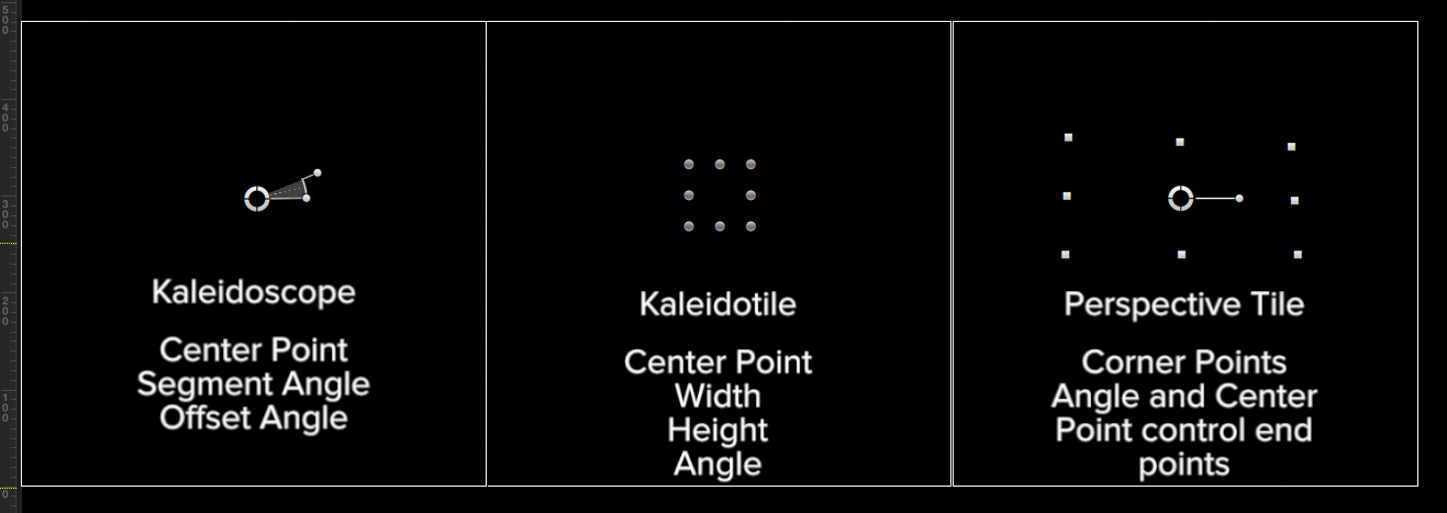
Tiling Filter OSCs
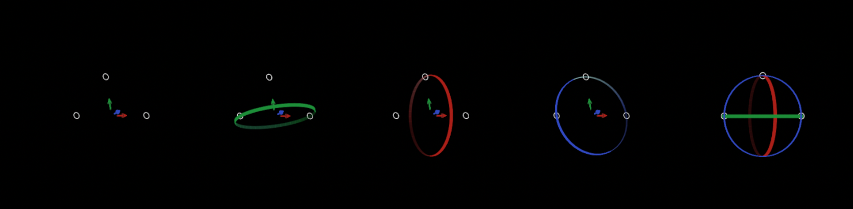
And as of Motion 5.2, the 3D Text OSC:
A list of Poke class filter OSCs:
- [Distortion] Black Hole, Earthquake, Fisheye, Fun House, Glass Block, Glass Distortion, Sphere
- [Stylize] Circle Screen, Halftone, Hatched Screen, Line Screen, Pixellate, Slit Scan, Slit Tunnel, Texture Screen
- [Glow] Light Rays
- [Tiling] Parallelogram Tile, Random Tile, Tile, Triangle Tile
Circle Blur, Bulge and Disc Warp use the same OSC but have differing parameter magnitudes for the circle control.
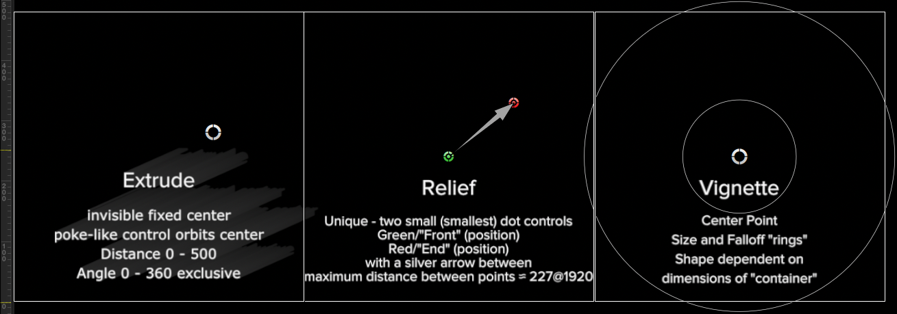
Droplet, Ring Lens and Vignette use the same basic OSC with differing parameter magnitudes and the Vignette is subject to the shape of its container (the dimensions of the image/video or of the group to which it is applied)—the “circle” controls are usually oval shaped.
Similar variants exist for Scrape, Target and Stripes. Just be aware that even though the OSC looks the same as another, the “scale” or magnitude of the parameters in use by that particular filter may not be the same as its relative. To further complicate matters, the parameter values *shown* in the inspector may not be the same as those passed behind the scenes to another object’s linked parameter.
Specifically, the Twirl > Twirl parameter shows -720° to +720° as its range in the filter’s inspector, but the values passed behind the scenes are -125.664 to +125.664. Those values might not be the least bit obvious, but what they come down to is 10 * 4π. The important value here is π and it is made obvious when the Twirl value is set to 180° and the value (revealed by using a Numbers generator whose Value parameter is linked to a Twirl Filter Twirl parameter) is 31.41592654…
If that doesn’t make any sense: by increasing the magnitude of the value, *more* decimal places become significant for precision math operations. [None of this information is documented and this is my best guess based on the information I’ve been able to ferret out.] Motion can be very precise!
As a quick example, let’s examine the Sphere filter. Its OSC is the same as Poke, a single center position indicator (or button)? Let’s say we want to change that OSC for use in FCPX to have a nice circle shape that defines the Radius parameter on the screen. Our best alternative filter to use is the Disc Warp filter. Disc Warp has the exact same onscreen representation as Circle Blur and Bulge, so why do we want Disc Warp?
Radius parameter translation between Disc Warp and Sphere is 1:1. Using Circle Blur it’s 10:1 and for Bulge, its 20:1. The respective “amounts” governed by the “ring” part of the control are 0—1000, 0—10000 and 0—20000, respectively.
So while they all look the same, the parameter change under control is much greater in Circle Blur and Bulge. Once the choice is made, it’s a simple matter to Link the Centers of both filters — and since they are the same parameter type only a single Link is needed to control both the X and Y of the center positions between the two filter OSCs — and the Radius/ring control value can be linked to the Sphere > Radius parameter without the need for scaling.
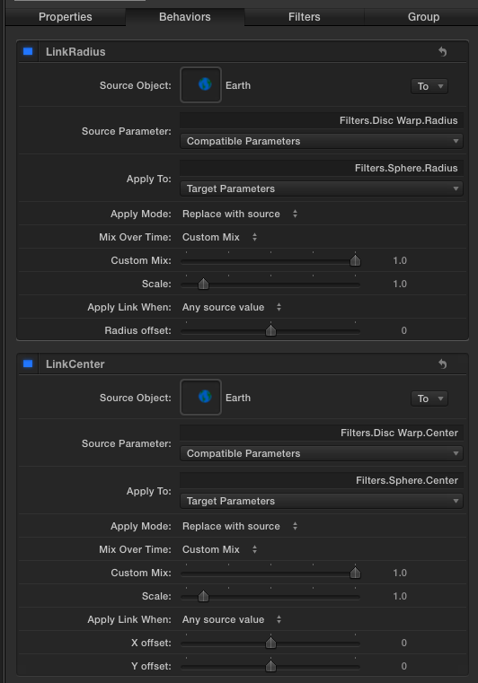
Now all you need to do is Publish OSC of the Disc Warp filter and not publish the Sphere OSC. With a simple substitution and a couple of Link behaviors, we’ve just enhanced the onscreen interface to the Sphere filter effect! In case you didn’t notice, we didn’t have to use Fixed Resolution. As a matter of fact, you may change the group to 3D if you like (and know how to create the rotating earth effect) using the same OSC.
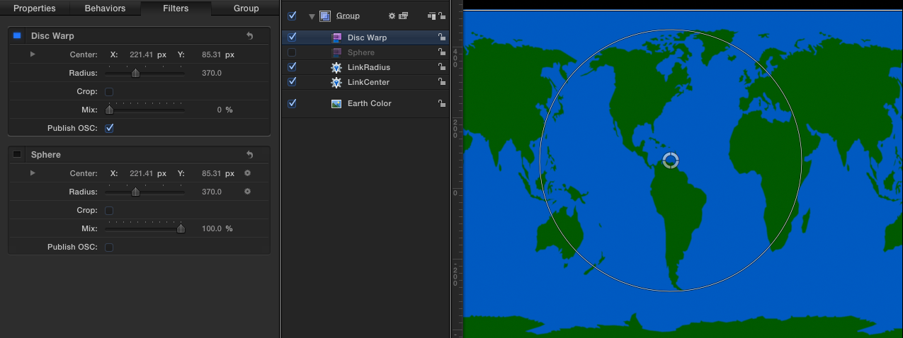
(Sphere filter turned off to show the Disc Warp ring)
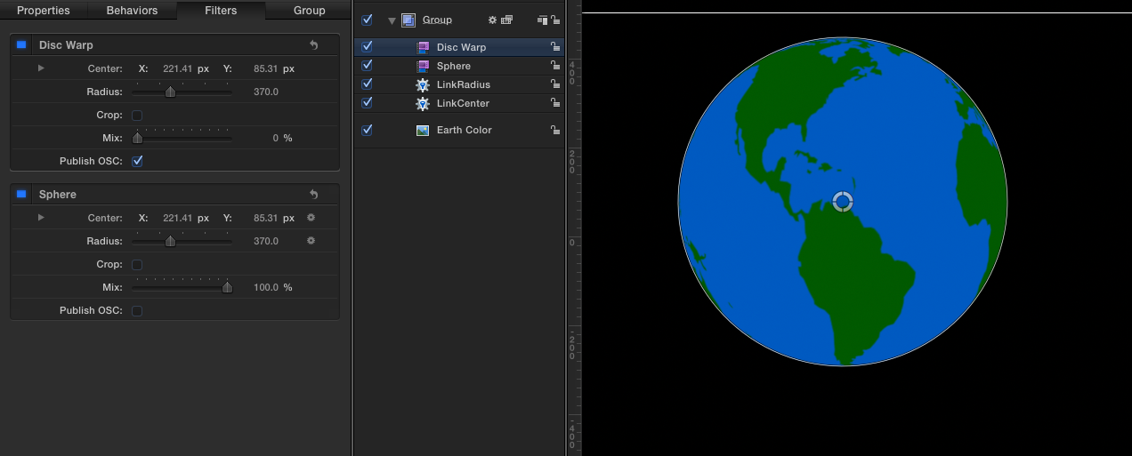
(The Sphere filter turned on)
The incidental OSCs
There are several generators that have OSCs that are publishable to FCPX. Unfortunately, they are only ever visible in FCPX and therefore practically useless (but not impossible) for developing in Motion. One of the most interesting is the OSC for Spiral Drawing (two meshed gears).
Included in the list of OSCs above is the 3D Text onscreen control. It is possible to use this control in FCPX and although it can be used to control positioning in FCPX’s viewer, that control’s positioning cannot be keyframed using the OSC (yet), at least not without combining it with another more traditional filter OSC. Rotational control can be keyframed. The technique used is to create a 3D character in a group by itself, then turning off the group.
Make the character large enough to respond to a mouse click near the actual object under control. You also need to make sure that the “OSC text” is Editable in FCPX. This OSC is only useful when no other onscreen editable text is used. Linking parameters between the 3D Text character used as the OSC is simply matching the character’s Position and Rotation to the object or group under control. I’ve only included it here for completeness.
A brief look back
In the first edit of this article, I was going to illustrate the use of the Perspective Tile OSC. In my last article, we used four separate Poke OSCs to control the corner points of a shape. To avoid restating the same basic material, you can download and inspect this variation that uses one Perspective Tile OSC instead. It can also be used as a generator in FCPX. [Download]
Developing a “HUD”
There is one more feature of OSCs that will very likely blow you away. It doesn’t matter if you resize a Fixed Resolution group, or simply scale the group, you can shrink or grow the group your OSCs are built in without affecting how they work with the rest of the scene. In other words, you can reduce your OSC layout to the size of a HUD (heads up display). How is this possible?
All OSC position parameters have a range from 0 to 1 no matter what the dimensions are of the object they are attached to, remember? The OSC “center” position will always be the same value no matter how its “domain” changes size. With respect to Group objects, that means either the actual dimensions can be changed as in the width and height parameters that become available when Fixed Resolution is selected, or when the object is scaled to a new size.
Motion allows both ways to set up the size of a group, and scaling can be keyframed. Our HUD design can be any size and moved to any location and the OSCs attached to it will always automatically follow the exact position within that group no matter what, it doesn’t change its parameter values or how those values interact with linked parameters in another group at another size. It will make perfect sense when you see it in action.
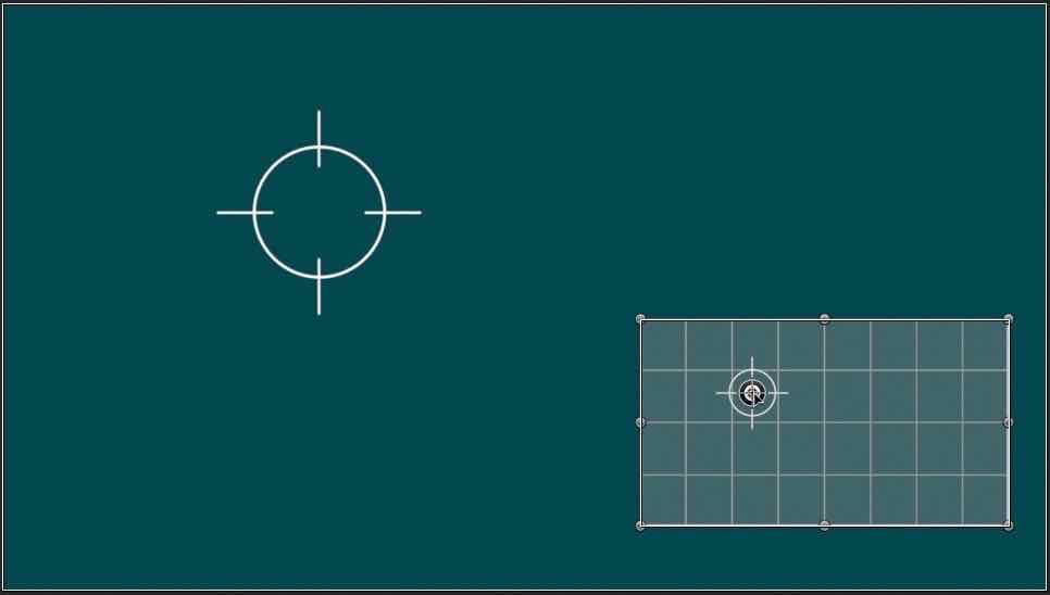
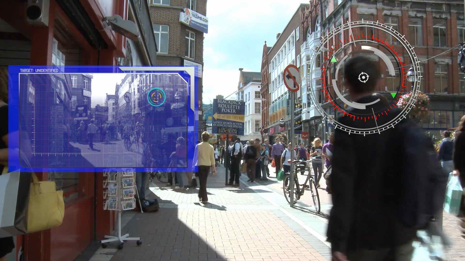
This week’s project “recipe” will be a simple “tracker” effect, a circle with crosshair lines with an OSC that can be keyframed to animate the position of the graphics. We will create an H.U.D. (heads-up-display or “hud”) effect that will contain the OSC and another copy of the target graphic on a grid background—two identical graphics that move in parallel with a single control without any special compensation. Most of the time, you will probably develop a HUD that will be turned off before rendering, but in this project, the HUD is actually meant to stay in the scene, basically, a barebones sci-fi type of effect:
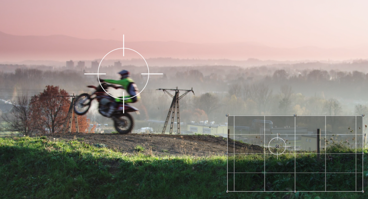
(Stock footage courtesy of Pond5)
Project design considerations
We will use two different filter OSCs as our onscreen controllers. We will use a Gradient Blur OSC (half of it) to control the position of the target graphic because it is smaller than the common Poke OSC and more graceful in this situation. To use 1/2 a Gradient Blur, we will simply link the position of one of the points (Point 1) to the position of Point 2 (the same can be done with the Relief filter OSC for an even smaller red “button”).
For the other OSC, we will use the Kaleidotile OSC. It is a rectangular control with eight control points plus its background region is used to reposition all eight control points at once (the entire control region is a position control). The Kaleidotile can be configured to control the scaling of our HUD design group as well as it’s positioning. We will be limiting its behavior so that the shape cannot be rotated and we will accomplish this by putting a Clamp behavior on the Angle parameter with the Min and Max values set to 0.
Note: in general, with an OSC combination design of this sort, filter “order” is important. That is, the Gradient Blur control in this project needs to be higher up in the layer list than the Kaleidotile OSC. In our Sphere demo above, the Sphere OSC needs to be below the DiscWarp OSC in Motion. Since the Sphere OSC is not published for FCPX, the order doesn’t matter in FCPX.
The “recipe”
Begin by creating a new 1920×1080 Generator in Motion. We’ll start by building the HUD graphics first.
To make what we are about to develop easy to see in the canvas, select the Project “layer” and in the Inspector > Properties, change the background color to (near) R:0 G:80 B:90 (a dark cyan color—it doesn’t have to be exact—just comfortable to look at). With the default black background of the canvas, it will be impossible to see the background of the grid used.
Select and rename the default Group layer HUDGraphics.
Add a Generator > Generators > Grid. In the Grid Generator inspector make these changes:
Line Color Opacity: 0.25 (dial down the disclosure triangle at Line Color to reveal it).
BG Opacity: 0.5
Line Width: 5
BG Width: 236
BG Height: 268
Draw a Rectangle and center it (Properties > Transform > Reset). In the Shape Geometry inspector dial down the Size parameter:
Width: 1916
Height: 1074
Roundness: 16
and in the Style tab:
Turn Off Fill (if on)
Turn On Outline
Width: 7
Close the HUDGraphics group and with the group still selected, type Command-Shift-G to create a new top layer group containing the HUDGraphics group. Name this new group OSC-HUD. Since we will be using an OSC Center parameter to control position, we have to set Fixed Resolution in the Group inspector.
Create another new (separate) top-level Group and name it HUDCntl (HUD control). Draw any shape and turn the shape off (this will set the group’s timing to the length of the project).
To the HUDCntl group, add Filters > Tiling > Kaleidotile. Set the Mix to 0 and select Publish OSC.
In the Kaleidotile inspector, right click on Angle and select Add Parameter Behavior > Clamp. Set the Min and Max values to 0. This will keep the OSC from rotating when the corner points are grabbed.
Select OSC-HUD. In Properties > Transform right click Position.X and select Add Parameter Behavior > Link. Go back to Properties > Transform and add a Link behavior to the Position.Y parameter. In the Layers List, name these links PosX and PosY respectively. Select one of the Links in the Layers List (that will switch the inspector to the behaviors inspector) and drag the HUDCntl group into the respective Source Object wells. Select the Source Parameter > Compatible Parameters and select Filter.Kaleidotile.Center.X and Y respectively. Set their X/Y offsets to -0.5. [If you’re unfamiliar with these, please see the first article in this series.]
When linking the Width and Height parameters of the Kaleidotile filter to the Scale X and Scale Y of the HUDGraphics group we run into another parameter mismatch. Trying to match the outline of Kaleidotile to the outline or bounding box of our graphics (grid, etc.) we need to adjust the Link Scale parameters so that the edges match.
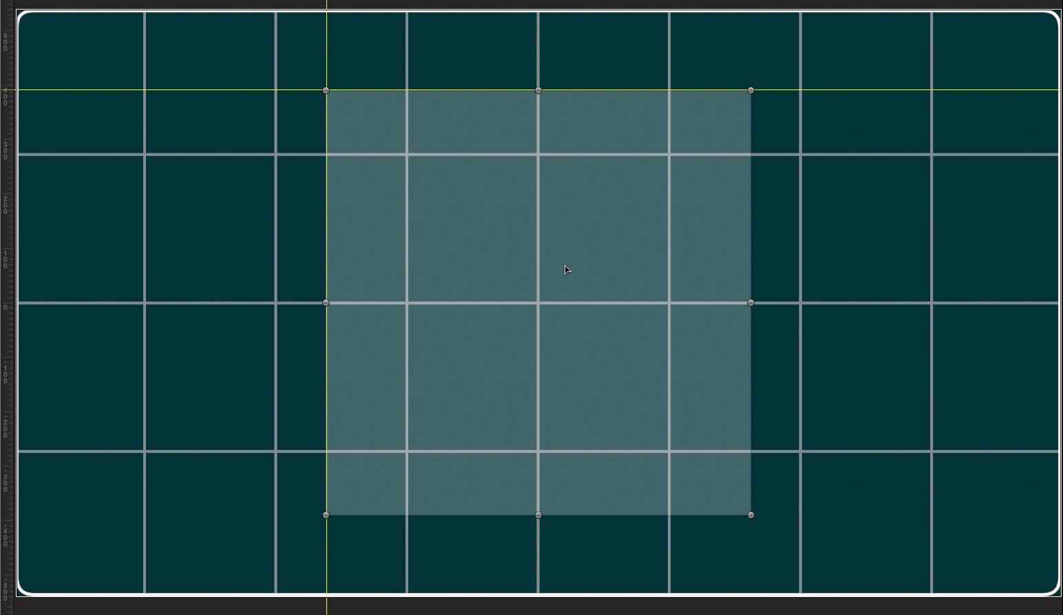
Select the Kaleidotile in the Layers list so that its OSC is available in the canvas and resize it to about one half the size of the canvas. If Rulers aren’t showing, type Command-Shift-R to show them and click on the vertical ruler and drag out a guide to the left side of the Kaleidotile size controls. Drag down a guide from the top ruler to the top edge of the Kaleidotile control.
Select the OSC-HUD group and Link the Properties > Transform > Scale X and Y parameters to the Kaleidotile Width and Height parameters (rename them ScaleX and ScaleY).
Now, slide the ScaleX Scale parameter slider left until the left side of the HUDGraphics lines up to the guide as closely as possible. Fine tune the value by typing in values (hint: it ends up being 0.52). Do the same with the ScaleY Scale (0.926) and when you resize the Kaleidotile OSC, the graphics should stay within “bounds.”
Normally, you would want to click and drag on the corner controls to help keep the aspect the same but it is not necessary to do so and it won’t break how the control works! [Tip: to get better fine tune control of sliders in Motion, drag out the Inspector pane wider which will max out at about two-thirds the total width of Motion’s window.]
Manually reset the Kaleidotile width and height parameters to 1920 and 1080 to reset the HUDGraphics aspect to its original dimensions.
[Aside:] If you go digging around in the underworld of Motion you will frequently find some unexpected results. It is often necessary to try and inspect values for objects that cannot be selected, particularly when OSCs are in use. When an object cannot be selected in the Layers List, it is impossible to view its parameters in the inspector while the OSC is selected, which it must be in order to use in Motion’s canvas.
The only avenue there is to inspect parameter values is to use a Numbers Generator, turn off the Animate option and Link the Value to the parameter under inspection. You can then watch how a parameter’s value behaves in the canvas, very much like a debugger would work. Long story short—you will find in many cases that all the digits will be correct, but the decimal point will be in the “wrong” place. The only logical conclusion is that some objects require more precision, thus more valid digits. Most importantly — don’t freak out — it’s normal. There are two ways to handle the discrepency: 1) offset the behavior’s Scale parameter, or 2) offset the behavior’s Custom Mix parameter (if available, as it is in Link).
So here’s the second method of figuring the scale values out. The parameter mismatch is Pixels vs Scale. Scale is in percent. If you take 100%/1920 for the X scale and 100%/1080 for the Y scale, you get 0.052 and 0.092 with an “extra” factor of 10 needed that is often present in many of the parameter “behind the scenes” values, values in this case required to bring the Kaleidotile edges in alignment to our graphic background.
The math works out perfectly, but truth be told, I used the procedure described above first and looked for the math that solves this “equation” afterwards just in case there were any questions as to “where did those values come from?” In contrast, when linking Kaleidotile width and height parameters to a Rectangle shape width and height, the result is a perfect 1:1 match.
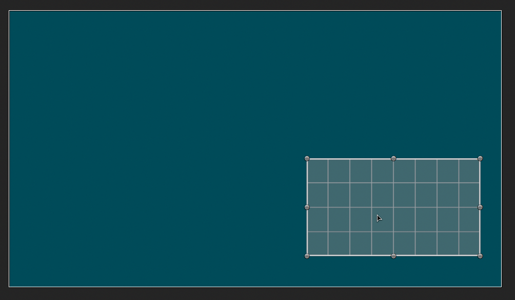
When you’ve gotten everything hooked up, select the Kaleidotile filter in the Layers list and grab a corner control in the Canvas and reduce the size to about one quarter the original size. Click anywhere in the background of the Kaleidotile OSC (light-gray region—it will “light up” when you mouse over the region) and drag it to the bottom right corner. If all the graphics follow like they should, you’ve done everything right.
Setting up the Target Graphics
Create a new top-level group and name it TargetGraphic.
Next draw a Circle (hold down option and shift keys) and center it. In the Shape > Geometry inspector:
Radius: 120
and in the Style tab:
Turn off Fill
Turn on Outline
Set Brush Color to White
Width: 6
Next draw a vertical line and center it. In the Shape Geometry inspector:
Control Points:
Point 1: X: 0 Y: 50
Point 2: X: 0 Y: -50
and in Style:
Turn off Fill
Turn on Outline
Brush Color: White
Width: 5
Type ‘L’ to create a Replicator. In the Replicator Inspector > Replicator Controls
Shape: Circle
Arrangement: Outline
Radius: 136
Points: 4
Cell Controls:
Check Align Angle
Adding the OSC control for the Target
Close the Replicator by clicking on its disclosure triangle and command-select the Replicator, the Line and the Circle and type Command-Shift-G to create a new group of the parts. Name the new group: GraphicParts.
Select the OSC-HUD group and add Filters > Blur > Gradient Blur. Set the Mix to 0%. Right click on Point 1 and Add Parameter Behavior > Link. In the Source Object well, drag and drop the OSC-HUD group. For the Source Parameter > Compatible Parameters, select Filters.Gradient Blur.Point 2. This will put both points together, Point 2 will be on top (Point 2 is always above Point 1) and show in the canvas and we will be controlling just that point in lieu of using the much larger Poke OSC. Name this behavior LinkPt1toPt2.
Select the Target Graphic group and in the Properties > Transform inspector create Link behaviors for the Position.X and Position.Y parameters. In the Behaviors inspector, drag and drop the OSC-HUD group. Set the Compatible parameters to Filters.Gradient Blur.Point 2.X and Y respectively and set the X offset/Y offset parameters to -0.5. Select the Gradient Blur filter in the Layers List and drag the button around the HUD area. Notice how the target graphic parallels this movement on the larger Canvas area.
Finishing up
Now, select the Target Graphic group again and option-drag a copy into the HUDGraphics group. The Linked parameters will copy along with the group so you won’t have to go through the process a second time. You’re done.
Try out your effect! Command-select both the Gradient Blur and Kaleidotile filters. In the canvas, click and drag the Gradient Blur control. Do both target graphics follow? The one in the HUD should be a microcosm of the one on the full sized canvas. Drag around the HUD by it’s background. The target graphic stays in the same location. Drag it around again and both targets maintain their relative relationships. (Is that cool? Or, what?)
Publish Parameters for FCPX:
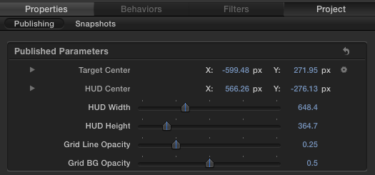
Select the Gradient Blur and Publish the Point 2 parameter. In the Published parameters inspector, rename Point 2 to Target Center.
Select the Kaleidotile filter and Publish Center, Width and Height parameters.
Select the Grid generator and publish Grid Line Color Opacity and Grid BG Opacity.
Select the Rectangle in HUDGraphics and publish the Outline Brush Opacity.
Here’s a snapshot of the published parameters:
[If you don’t have Motion or you didn’t feel like doing the project yourself, you can download today’s project here.]
Wrapping up
I’ve had to “keep it simple,” but most of the fun of Motion is dressing up projects to make it look like more than it really is.
Obviously, I couldn’t fit everything else about OSCs into these last three articles. Basically, you have several filter OSCs available to help you control various aspects of whatever you want to control by linking the user interface element parameters with any other parameter of any other object you want (that Motion allows).
If you’re building something for yourself it can be as outlandish as you want, but if you’re developing an OSC or combination of OSCs for a general user public the best practice would be to use those elements that have some kind of corresponding meaning between the control and those items under control.
There are OSCs that help a user control various aspects of a visual effect and there are those that can be part of the animation even though the actual OSC itself is never rendered. In the case of a HUD, you could have just that, a HUD that would have its visibility turned off before rendering the storyline. Some uses might be a color picker, rotation guides, or even one that could be used to control the limbs of a cartoon/animated character (try Page Curl—one for each arm and leg).
A HUD is best used for OSC combinations that need grouping together. Another use for HUDs might be for more “sci-fi” effects where actions in the HUD are immediately reflected in the “real world” environment. In these cases, and as outlined in today’s recipe, one action can reflect many others in many planes at the same time (hint).
Some other uses for OSCs? Circle Blur/Disc Warp types for creating an animatable circular “spot” with drop zone (requires using a shape mask linked to the control’s ring—download demo is a Title). Extrude is great for controlling rotation and displacement (within a fixed range), but really requires another Poke-like control to mark a center point (it doesn’t have a center indicator). You could even use multiple Extrudes at different fixed distances (using Clamp) to create a 3D rotation control. It is possible to link Perspective Tile corners to the Four Corners parameters of all the different object types available to make a distortion control, and the list goes on…