From Peter Wiggins (original publisher @ fcp.co)
If you ever want to build an adjustable line or shape in Motion for use in Final Cut Pro, there is only one way to get the On Screen Controls to work. In the second part of the series on OSCs, our resident Motion expert, Fox Mahoney shows us how to control shapes in plugins for FCPX. He’s also very kindly included a link to the completed template!
Controlling Shapes: The mysteries of OSC in Final Cut Pro X revealed, Part 2


In part one, I illustrated the basic workflow for aligning a filter On Screen Control (OSC) with an object in the viewer/canvas—behavior that is not very “Motion-like”. I explained how to compensate for coordinate disparities between filter controls and objects and the necessity of using Fixed Resolution to restrict the scaling of the movement of those controls to match the current project. These are all side effects of using an “instrument” in a manner for which it was not originally designed. FCPX automatically resizes (based on aspect ratio) the template so that for any size 16:9 project, the OSCs work consistently.
In this installment, we’ll branch out slightly from the last project and put the points of a shape under OSC control for use in Final Cut. In order to move shape points in FCPX we will need to use the Track Points behavior. The complication here is that you can only track a video or an image. You cannot track a shape or use an OnScreen Control to drive the Track Points behavior. So here we go down the rabbit hole again!
Retro Done Right
If you’ve never seen the Retro generator, it’s in the Textures category of the Generators browser. The standard Retro generator provided by Apple looks like:

And that’s it! It does nothing, no options to change color or any other type of parameter control. It’s basically a background image and a bit of a disappointment but can be taken as inspiration to make it better.
When you complete this project, you’ll have a template that you’ll be able to customize in FCPX: the shape (and positioning), color (tint), the roundness of the corners, feathering the solid, adjusting the width and transparency of the outline, and setting the opacity of the background so this could be used as the background of a Title overlaid on the storyline. In other words: we will have created something more useful!

The best way to do a project like this one is by formula. Once you get the process down, you’ll always do it the same way. For this project, we’ll add the all parts then wire them together. For these types of projects (multiple point control), it is extremely useful to change the names of objects added to correspond to each other.
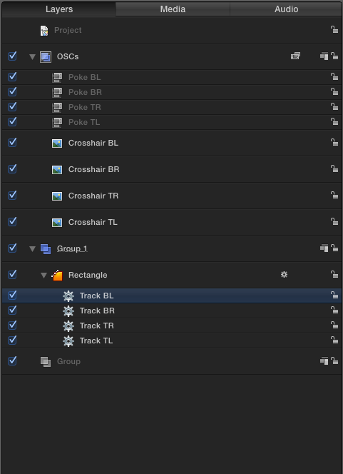
We will be creating a four cornered shape requiring four Poke filters, four crosshair/target images that we’ll get from Motion’s Content Library and four Track Points behaviors. Changing their names to match the four corners by adding TL, TR, BR and BL (representing topLeft, topRight, bottomRight and bottomLeft respectively) will make keeping track of individual parts simple.
It is not necessary to follow this regiment—Motion is a very flexible application, but this is essentially how our “alphabet” is arranged. It can be a little tedious and “label tagging” will make this method is the shortest way though the process with the least chance of committing errors.
In Motion, start a new Generator project. Click twice on the ‘+’ symbol at the bottom right corner of the Layers column to add two more “top level” groups. On the bottom most group, double click the name and change it to Background. The middle group: Main. Topmost group: OSCs. While the OSCs group is selected, in the inspector > Group Controls, set Fixed Resolution (we will be adding objects to this group so we do not have to be concerned about the Timing as we were in part one).
Go to the Filters icon (to the right of the “gear”) and select Distortion > Poke. With the Poke filter selected in the Layers list, type Command-D three times to make four total instances. Double click each name and change the labels to Poke TL, Poke TR, Poke BR, Poke BL (in top-down or bottom-up order; however you “see” the stacking order in Motion — in this tutorial, I use bottom-up order).
Next: go into the Library (click the tab to the immediate left of “Inspector”) in the inspectors panel. Find and select the “Content” category.
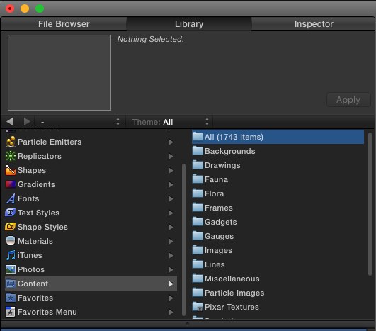
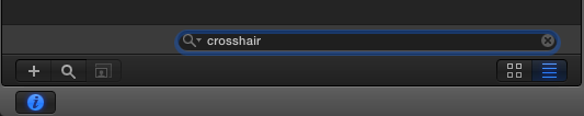
Click the magnifying glass at the bottom of the column and in the search field type: cross (or crosshair).
And now for the whys and wherefores…
In the list that appears, find Crosshair Minute.png and click the Apply button at the top right of the Library pane four times. [That’s minute as in very small, not time ;)]. In the Layers list, double click on each crosshair’s name and change them to Crosshair TL, Crosshair TR, Crosshair BR, and Crosshair BL – in a matching order as the Poke filters.
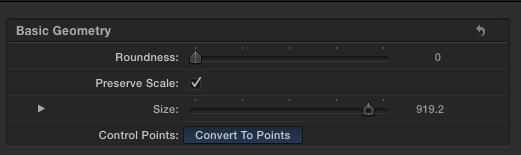
The next thing to do is draw the shape. Select the “Main” Group. You have two options: 1) you can draw a Rectangle shape, or 2) you can select the Bezier pen tool and rough out a four corner shape in the canvas. If you choose option 1, you will need to go into the Shape inspector > Geometry tab and click on the Convert to Points button. If you choose option 2, neatness does not count. All the points are going to be under OSC control when the project is done anyway.
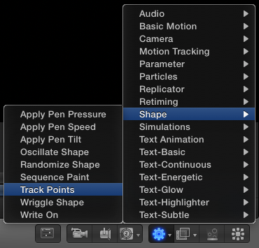
With the Shape still selected, click on the Gear (Behaviors) icon and select Shape > Track Points.
We can only use one tracker per Track Point behavior per control point on the shape, so we’ll need four of them. With the Track Points selected in the Layers list, type Command-D to duplicate three more times. Rename the Track Points with the TL, TR, BR and BL endings as you did with the other labels above.
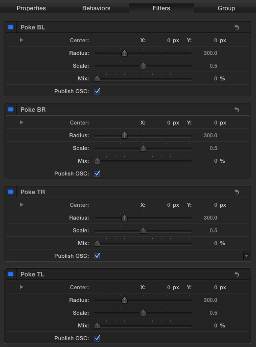
Select any Poke filter. If the Library is still open, click on the Inspector tab. The inspector should display all of the Poke filters together since they are attached to a single object (the OSCs group). Click on all four of the Publish OSC checkboxes to select them. Set all four Mix parameters to 0% (so that the crosshair images are not affected by the normal action of the filters).
Select the first Crosshair image in the Layers list. In the inspector, click the Properties tab then right click on the Y parameter and select: Add Parameter Behavior > Link. Go back into the Properties tab (the inspector automatically switched to the Link behavior) and right click the X parameter > Add Parameter Behavior > Link.
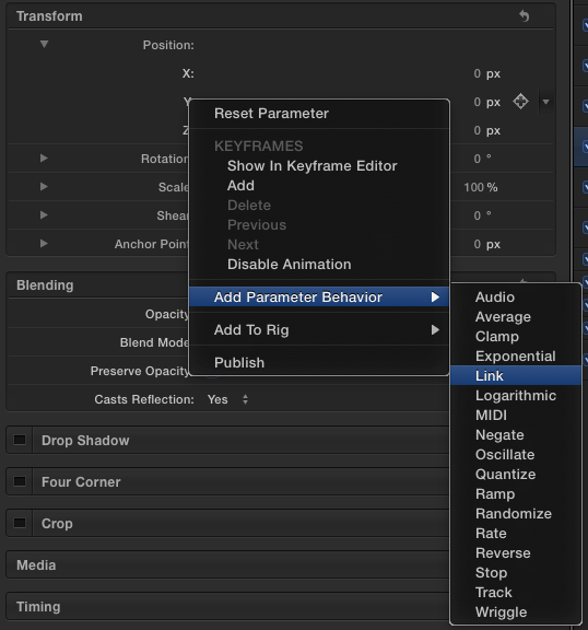
Choosing the Y parameter first will arrange the Link Y parameter in the inspector below the X parameter (behaviors are added to an object in an ascending order as they are added). Select the two Link behaviors and Option-Drag copies to the other three Crosshair images. Rename each of the Link behaviors in this fashion: TL X, TL Y (etc.) using the “orientation” abbreviation as the name paired with the parameter (X or Y) for each set of Crosshair Links. It does not matter that each set shares identical names.
We will do the same with the Crosshair images as we did in Part 1 and connect them to the Poke filter OSCs.
Select one of the Crosshair Link behaviors (start at one end or the other, we’re going to do this in order). I like to start at the bottom and work upwards because each step becomes shorter as you go. In my list, that will be the Crosshair TL image. Select it and select the behaviors tab in the inspector. In both Source Object wells, drag and drop the OSCs group. Since the Link behaviors are named by the same suffix used for the crosshair image, it will be easy to keep track of which filter Center parameter to use for each Link instance.
I will use “TorB” to refer to the TL, TR, BR, or BL references. All you have to do is go through and match the Poke OSCs to the Crosshair image position parameters.
For each Link behavior, select the Source Parameters > Compatible Parameters menu and select Filters.Poke TorB.Center.Y and Filters.Poke TorB.Center.X parameters respectively. Then, the same as in part one, adjust the X and Y offsets at the bottom of each Link behavior pane and set them to -0.5.
When you’ve done this for each crosshair image, select its corresponding Poke OSC and drag it on the canvas to roughly its intended position (it doesn’t have to be exact — just near). Otherwise, they’re just stacked in the center of the canvas and we’re killing two birds with one action by moving them at this point instead of sorting them out afterward.
The Track Points
Select a Track Point behavior. The inspector should adjust automatically to show the behaviors attached to the shape object. If not, make sure the Inspector tab is selected in the Inspector column.
For each Track Points behavior do the following:
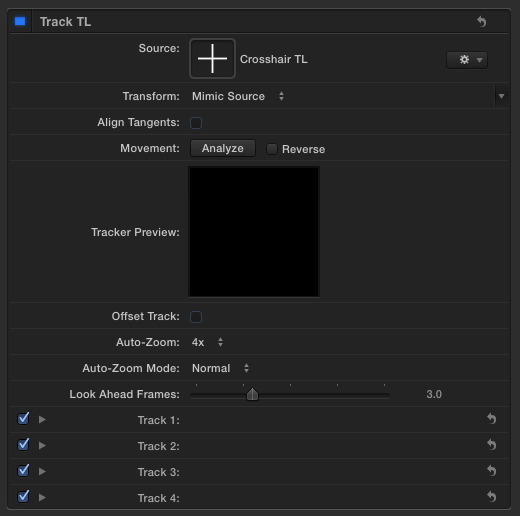
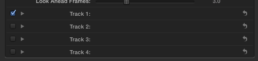
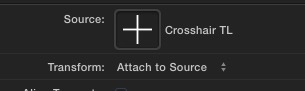
Select the individual Track Point you will be working on in the Layers list. Add the corresponding (TorB) Crosshair image to the Source drop well. Additional parameters will appear at the bottom of the inspector. You’ll see Track 1, Track 2, …, Track 4 and they are all checked!
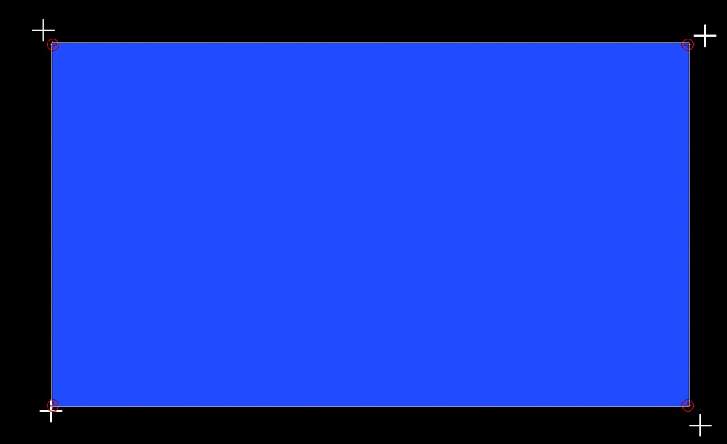
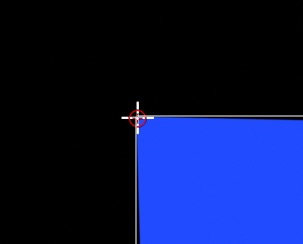
Take a look at the image below. On each shape control point, you’ll see a small red circle with a ‘+’ inside. These are the actual trackers used by Motion. We need to get these markers aligned to the Crosshairs.
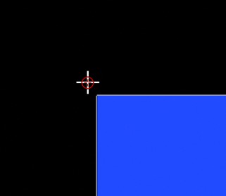
Uncheck one of the Track # points and notice in the canvas which tracker turns off. Turn off all the Track # parameters except the one that corresponds with the Crosshair you are trying to match (this is the primary reason for all the labeling changes when setting this project up!)
Once you’ve selected the Track Point tracker with the appropriate “corner,” you will need to click on the reset icon Image.OSC fcpx pt2 01 The reset action is a little touchy so you might have to click on it more than once (concentrate on the arrowhead side of the icon), but when you successfully reset the parameter you will notice the tracker in the canvas will align with its corresponding Crosshair.
Once that happens, change the Transform parameter to “Attach to Source.” You will notice that the point of the shape will snap to the Crosshair center.
Select the matching OSC Poke filter and drag it around the screen. The shape’s corner point should now follow.
Finish up the rest of the Track Points in the same fashion.
When testing this out in Motion, command-select all the Poke filters to make the controls appear in the canvas at the same time.
Turn off the visibility of the OSC group (all the Crosshair images will disappear but the published OSCs will remain visible in Motion when selected and FCPX).
To create the off-edge “outline” all you need to do is duplicate your original shape object. Select it in the Layers list and type Command-D. All of the Track Points will be copied over to the new shape and all the “wiring” will be intact. Go into the Shape’s inspector > Style panel and turn off Fill and turn on Outline. In the Layers list, select one of the outline copy’s Track Point behaviors (all will appear in the inspector) and for each one, go to the Track point that is checked and dial down the disclosure triangle. Make the following changes for each:
TL X -20 Y-20
TR X -20 Y 20
BR X 20 Y 20
BL X 20 Y -20
Finishing up and creating the template
Select the Background group and go into Generators and select Generators > Color Solid.
To colorize this template, a single Tint filter will be used. To do that, select the Main group and the Background group (you may have to close both groups’ disclosure triangles to make this work) and type Command-Shift-G to create a new group with both of the selected groups enclosed. With this new group selected, add a Filters > Color Correction > Tint filter. In the Tint filter inspector, set the color to a light orange. Right click on the Tint Color (label) and select Publish from the popup menu. Publish the Tint Intensity parameter as well.
This next step will conform the luminosities of the three main elements (solid shape, outline, and background) by setting them all to pure white. For the solid, set the Fill Color; the outline, set the Brush Color and the Color Solid, set the Color parameter. To each of these objects, add a Filters > Color Correction > Hue/Saturation filter. Since we will be using the Value parameter of each of these filters, we will need to limit the ranges from 0 to 1.0 by rigging them (Value allows a maximum of +2.0 which is too much!)
Right click on the Value parameter of the Hue/Saturation of the solid shape and Add to Rig > Create New Rig > Add to New Slider. Name the Slider in the Layers List: Solid. Slide the Shape.Hue/Saturation.Value parameter in the Rig widget to 0, then slide the Solid slider all the way to the right. Set the Shape.Hue/Saturation.Value parameter to 1.0. Finish off by moving the Solid slider to 75.0 (you should see the color of the shape change to a pale orange). Right click on the Solid slider and select Publish.
Right click on the Value parameter of the Hue/Saturation of the Outline version and Add to Rig > Rig > Add to New Slider. Name the Slider in the Layers List: Outline. Slide the Outline.Hue/Saturation.Value parameter to 0; slide the Outline slider all the way to the right and set the Outline.Hue/Saturation.Value parameter to 1.0. Move the Outline slider to 50.0. Right click on the Outline slider and select Publish.
Right click on the Value parameter of the Hue/Saturation of the background Color Solid and Add to Rig > Rig > Add to New Slider. Name the Slider in the Layers List: Background. Slide the Color Solid.Hue/Saturation.Value parameter to 0. Mover the Background slider all the way to the right and set the Outline.Hue/Saturation.Value parameter to 1.0. Move the Background slider to 0.85. Right click on the Background slider and select Publish.
Select the Solid shape and in the Inspector > Geometry tab, publish Roundness. Select the Style tab and publish Feather and Fill Opacity.
Since we want the Outline to have the same roundness as the shape, select the Outline shape and in the Geometry tab, right click on Roundness and Add Parameter Behavior > Link. In the Source Object well, drag and drop the solid shape layer from the Layers list. Since the parameters are matching, Motion will automatically select the correct corresponding parameter in the Source Parameter:Compatible parameters selection. We do not need to (and should not) publish the Roundness parameter of this object since it is linked to another object. Select the Style tab and publish Brush Outline and Opacity.
Select the Color Solid generator and in the Properties tab of the inspector, publish Blending > Opacity.
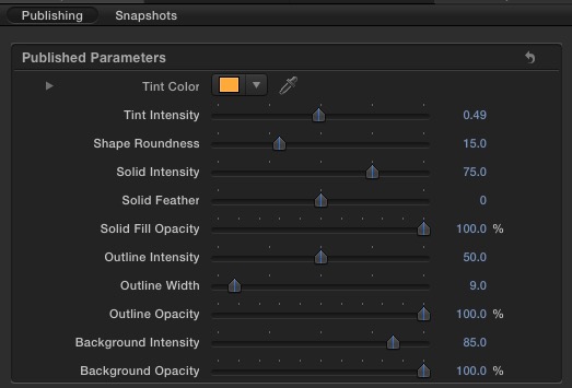
Select the Project “layer” in the Layers list > Project tab > Publishing sub-tab. Drag the Color parameter to the top of the list and drop it. It should be positioned at the top of the list. Double click on the label and change the name to “Tint Color.” Drag the Intensity parameter underneath Tint Color. Rename it “Tint Intensity.” Roundness gets moved into third and renamed Shape Roundness. Solid moves into fourth and renamed Solid Intensity. Follow it with Feather (renamed Solid Feather) and Fill Opacity. Rename Fill Opacity: Solid Opacity. Next the Outline parameters: Intensity, Width and Brush Opacity renamed Outline Intensity, Outline Width and Outline Opacity. Background and the last Opacity should be renamed Background Intensity and Background Opacity respectively.
Here’s our published parameter list:
Save the generator. Name it Retro Done Right and select the Textures category (that will place it in with the original Retro generator).
Enjoy!
If you doubt there is any other use for this information, here is almost the exact same project as outlined above. I’ve included it for download and study if you like. Be aware: when you change its shape, not everything follows until there is a frame advance, or you hit Play. (It’s a typical behavior of Replicators using “Geometry” in Motion).

Download the free template here: sc_RetroSign
Written by Fox Mahoney
—F•X
Many more templates to download on FCPXTemplates.com
Take a look at YouTube.com/fxmah for more templates & tutorials.